COTS PRODUCTS > COTS DIGITAL / ANALOG PRODUCTS > ARINC - 429 AVIONICS PRODUCTS > AT-USB-429
 
Portable USB Device
On Board resources (200 MHz processor, 64Mbytes RAM,16Mbytes Flash, 256Mbytes NAND Flash)
Available in a combination of 2Tx / 4Rx Channels
GPS Synchronization Capability (optional)
8 User programmable Discrete Ios
Supports up to max 12 Channels
  > 4 Transmit Channels
> 8 Receive Channels
Configurable for High Speed/Low Speed
128 x 32 bit Static RAM Interface on each Arinc429 node
Programmable interrupts Receive Data time-stamping
Transmit Data Scheduling (Asynchronous/Synchronous) messages
Two 32 x 32 Transmit FIFO on each Arinc429 node
Graphical User Interface Software for Bus Analysis and Simulation
Software Driver support Windows XP, Windows 7, Linux, RT Linux
 

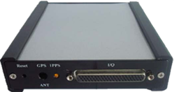
The AT-USB-429 module is a small, portable, USB device that provides a flexible, powerful ARINC429 avionics data bus interface for the development and maintenance of commercial avionics. The unit is designed to transmit and receive messages up to 12 channels. Each channel is software configurable for high or low speed (12.5k or 100k bits per second) and ARINC429 protocol requirements. The ARINC data word can be decoded and sorted based on the Label and SDI bits and stored in RAM and/or FIFOs. Having extensive functionality, they are used to communicate with, simulate, test, and monitor ARINC429 equipment and systems. The unit has onboard resources to compute time tags, handle data scheduling and offload the host from ARINC communication overheads. The unit comes with powerful software that reduces development time. All data bus functionality is supported from our advanced API (Application Programming Interface) and VIP (Virtual Instrument Panel).

Hardware

The AT-USB-429 module can be configured up to 2 nodes with ARINC429 controllers from DDC, each node containing 2 Transmit and 4 Receive channels, providing a maximum of 12 channels. Each controller has a 128 x 32 bit static RAM, four 32 (words deep) x 32 (bit) Receive FIFOs and two 32 (words deep) x 32 (bit) transmit FIFOs. Look-up tables loaded into RAM enable the modules receive circuitry to filter and sort incoming data by label and destination bit as well as provide multilevel data specific interrupts or hardware triggers. The receive channels allow for the storage of all selected Labels with status and time tag information (optional) appended to each word. The receivers allow for filtering and multi-storage modes of Data Words. The transmit channels operate via a transmit “instruction stack” which allows scheduling of data transmissions and reduces the need for host computer intervention. The discrete channels contain control I/O registers that are memory mapped and can be accessed in real time.

Power

The unit contains a DC power jack for connection to an external +12V power source. The DC jack is designed to interface with off-the-shelf AC adaptors.

Software

The AT-USB-429 software includes Drivers & APIs. The product comes with a powerful set of library functions to access the entire ARINC429 functionality. The drivers are designed in a modular fashion consisting of component functions and application functions. The user’s test program can be developed with few calls to the driver, by using the set of Application functions provided. Driver and high-level API libraries for Windows XP, Windows 7, Linux, RT-Linux are available. Sample applications are included.

ARINC429 Interface
Supports up to 12 ARINC429 channels
  > 4 Transmit Channels
> 8 Receive Channels
128 x 32 bit Static RAM interface on each ARINC429 controller
Programmable Interrupts
Configurable Bit Format Control
Transmit Interface
Programmable 12.5/100KHz bit rate
Two 32 (words deep) x 32 (bit) Transmit FIFOs on each ARINC429 controller
Major/Minor frame scheduling
Independent data transmit by each channel
Programmable data transmit rate for each channel
Transmit FIFO Status Indicators
Synchronous word transmission
Programmable Inter word gap
Receive Interface
Four 32 (words deep) x 32 (bit) Receive FIFOs on each ARINC429 controller
Receive data rates can be programmed for channel 0 and 1 independent of channel 2 and 3 in each ARINC429 controller
Reducing Receive Data Latency
Label and Filtering & Sorting of data
Storage of data
Parity Error Checking & Reporting
Receive FIFO status indicator
Time tagging of received messages
Diagnostics
Power-up Self test with status reports
Testing of Memory Elements
Testing Transmit/Receive functions
Interrupt Function Testing
Wraparound Test for each channel
Error Conditions
Sequence Error
Address Error
FIFO Overflow Error
Receive Data Parity Error
ARINC Clock Error
Discrete Channels
8 Discrete Inputs, TTL (0-5V)
8 Open Drain Discrete Outputs, TTL (0-5V), max current of 100mA
GPS Receiver (optional) for Synchronization
GPS receiver on-board for Synchronization
Synchronization control through software
Synchronization of on-board time tag counters with GPS time
32 bit micro-second time tag counter synchronized with GPS
Separate GPS antenna provided along with the unit
Software Support
Driver and high-level API libraries for Windows XP, Windows 7, Linux, RT Linux
Physical
Durable Enclosure with covers for 429 connectors
Approximate dimensions (135mm x 155mm x 32mm)
Environmental
Operating temperature: 0° C to +50° C
Storage temperature: -20° C to +70° C
Power
+12V External Powered through AC Adapter
Warranty
1 year limited warranty
 
CORPORATE   ABOUT   FOLLOW US ON
AdTEC Electronics Inc.
4677 Old Ironsides Drive
Ste 230 Santa Clara
California 95054, USA
 
AdTEC Electronics specializes in providing end-to-end custom product design & development encompassing System, Mechanical, Board Electronics, Chip design, Firmware and Application Software Engineering. Our design capabilities include design for testability and rugged design to meet both commercial and stringent regulations.
 
HOME ABOUT US COTS PRODUCTS SERVICES & SOLUTIONS SUPPORT & RESOURCES NEWS & EVENTS BLOG CONTACT US
AdTEC Electronics Inc.