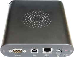
COTS PRODUCTS > COTS DIGITAL / ANALOG PRODUCTS > MULTI PROTOCOL AVIONICS PRODUCTS > AT-USB-MPAC
 
Portable USB Device
On Board resources (200MHz processor, 64Mbytes RAM, 16Mbytes Flash, 256Mbytes NAND Flash)
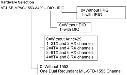
MIL-STD-1553B – Optional
  > IPC1553 – Next generation 1553 core
  > 1 Dual Redundant MIL-STD-1553 Channel
  > Each channel is independently programmable as either
  > Bus Controller, Remote Terminal or Bus Monitor
  > 1 Complete message programmability
  > 48-bit/100ns Time tagging
  > Direct or Transformer Coupled Bus Interface
ARINC429 – Optional
> IPC429 – Next generation 429 core
> 8 Transmit and 8 Receive Channels
> Configurable for High Speed (100 Kbps) or Low Speed (12.5Kbps/50Kbps)
> Upto 256 Label memory for each Receive channel
> 128 Word for Tx and Rx FIFOs for each Transmit and Receive channel
> Asynchronous and Synchronous messaging
> Programmable Interrupts
> Programmable Refresh rates of 20ms to 200ms
> Label selective trigger for Capture/Filtering and SDI filtering
Optional 6 discrete inputs and 6 discrete outputs
IRIG-B Time Code Input (Digital/Analog)
IRIG-B Time Code Generator/Output (Digital)
GPS Synchronization capability (optional)
Software Driver Support for Windows 7 and Linux are available
 

The AT-USB-MPAC family of products provides the highest level of performance and flexibility on various hardware interface architectures and custom platforms. Integrating MIL-STD-1553B, ARINC429 and Digital I/O channels, all in a single unit, it offers the ideal platform for test & evaluation of avionics systems and sub-systems. On board six discrete inputs and six discrete outputs, IRIG-B Time code Input/Output is also available. An onboard IRIG-B time code decoder and generator allow users to accurately synchronize single or multiple USB MPAC modules to a common time source.

Software

The AT-USB-MPAC software includes Drivers and APIs. The module comes with a powerful set of library functions to access the entire MIL-STD-1553B and ARINC429 functionality. Source code is provided for samples, and detailed documentation. The drivers are designed in a modular fashion consisting of component functions & application functions. The user’s test program can be developed with few calls to the driver, by using the set of Application functions provided. Driver and high-level API libraries for Windows 7, Linux are available.

MIL-STD-1553B Interface
1553 Bus Controller (BC)
64K Words of memory per channel
Automatic retries on alternate bus
Inter-message gap times from 8µs to 65ms
Frame auto repeat up to 5s
Programmable response timeout up to 130µs
Major and minor frame content and timing
Modify messages, data or setup while card is running
Detects and reports 1553 errors
Synchronize BC operation to external time source
Programmable BC timeout values
Flexible support for data streaming or bulk data transfer
1553 Remote Terminal (RT)
31 Remote terminal control
Programmable response time and status word bits
Programmable command illegalization
Selectable interrupts upon multiple conditions
Support for all 1553B mode codes
Programmable Single Message or double buffering or circular buffering
BUSY Bit programmable by sub address
Alpha numeric message ID
1553 Bus Monitor (MT)
Word monitor per word basis
Selective message monitor & time stamping
Dynamic data update
Message Periodicity
Bus error status
Bus load
Unique Message identifier
Record and Replay option
Advanced Bus Error Detection to Isolate Bus Failures
100% data capture at full bus rates
Programmable data logging to file
Sequential record includes: command/status/data words, time-tag, errors, bus, and response time(s)
ARINC429 Interface
Supports up to 16 ARINC429 channels
> 8 Transmit Channels
> 8 Receive Channels
128 Word deep FIFO on each channel
Programmable Interrupts
Built-in Fault Detection Circuitry
Set parity per channel (odd/even/data)
Sync output on all or selected messages
Handles periodic and transfer protocols
Message filters and schedules
Data Rates: 12.5/50 Kbps in low speed and 100Kbps in high speed
Standard input levels: ±6.5 to ±13 VDC
Filtering: Label and/ or SDI
Parity: Odd, even or none
Error reporting: Parity
Output levels: ± 10 VDC
Discrete I/O
Optional Six Discrete Inputs & six Discrete Outputs
GPS Receiver (optional) for Synchronization
GPS receiver on-board for synchronization
Synchronization control through software
Synchronization of on-board time tag counters with GPS time
Separate GPS antenna provided along with the unit
Software Support
Driver and high-level API libraries for Windows 7, Linux
Sample applications provided
Physical
Durable Enclosure with covers for connectors
Environmental
Operating Temperature: 0°C to +50°C
Storage Temperature: -20°C to +70°C
Warranty
1 year limited warranty
 
CORPORATE   ABOUT   FOLLOW US ON
AdTEC Electronics Inc.
4677 Old Ironsides Drive
Ste 230
Santa Clara, CA 95054
USA
 
AdTEC Electronics specializes in providing end-to-end custom product design & development encompassing System, Mechanical, Board Electronics, Chip design, Firmware and Application Software Engineering. Our design capabilities include design for testability and rugged design to meet both commercial and stringent regulations.
 
HOME ABOUT US COTS PRODUCTS SERVICES & SOLUTIONS SUPPORT & RESOURCES NEWS & EVENTS BLOG CONTACT US
AdTEC Electronics Inc.